RNS315
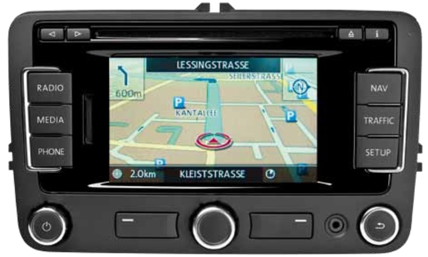
The radio and navigation system "RNS315".
PR-Numbers (Equipment codes) for RNS315:
- SG3, Installation of RNS 315 instead of RNS 310
- 7T8, Navigation system "RNS315 NAR"
- 7UC, Navigation system "RNS315" (integrated data storage device)
- 7UK, Navigation system "RNS315 SAM"
- 7UM, Navigation system "RNS315 China"
Factory installed card:
- 7QL, Integrated data storage device for Western Europe
- 7QM, Integrated data storage device for Eastern Europe
Content
Images
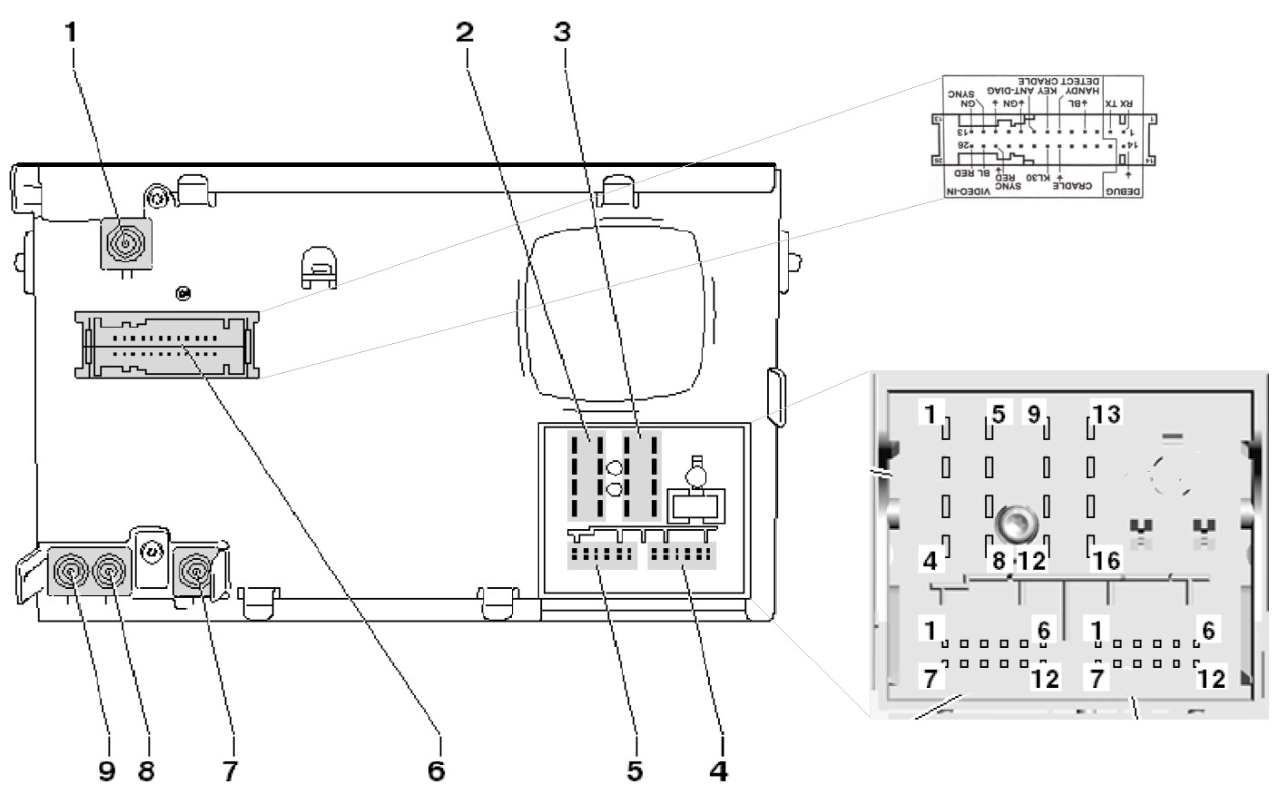
The ECU images below are intended to get an idea and to show of which ECU it is. Furthermore, they could help if the question of the arrangement of the components is in the room after too fast disassembly or desoldering. The most frequently asked question in this context is:
"Where is Pin 1?". The photos shown can not cover all of the ECU revisions, so they should be seen as examples.
Front face
Connector

Circuit board top

Pin assignment
| Slot | Slot-description | Comment |
|---|---|---|
| Connection for digital radio reception (DAB) | Optional | |
| 2 | Multi-pin connector, 8-pin, for loudspeaker outputs | |
| 3 | Multi-pin connector, 8-pin, for voltage supply wires and CAN bus | |
| 4 | Multi-pin connector, 12-pin, for telephone and microphone signals | |
| 5 | Multi-pin connector, 12-pin, for CD changer control and CD audio input signals | |
| 6 | Multi-pin connector, audio and video, 26-pin | |
| 7 | Navigation aerial connector | double SMBA, coding C, impedance 50 ohms, colour signal blue |
| 8 | FM 2 radio reception aerial connector | double SMBA, coding B, impedance 50 ohms, colour cream-white |
| 9 | AM and FM radio reception aerial connector | double SMBA, no coding, impedance 50 ohms, colour cream-white |
Multi-pin connectors:
| Slot | Pin | Description | Comment |
|---|---|---|---|
| 2 | 1 | Rear right loudspeaker, positive | |
| 2 | 2 | Front right loudspeaker, positive | |
| 2 | 3 | Front left loudspeaker, positive | |
| 2 | 4 | Rear left loudspeaker, positive | |
| 2 | 5 | Rear right loudspeaker, negative | |
| 2 | 6 | Front right loudspeaker, negative | |
| 2 | 7 | Front left loudspeaker, negative | |
| 2 | 8 | Rear left loudspeaker, negative | |
| - | |||
| 3 | 9 | CAN bus high | |
| 3 | 10 | CAN bus low | |
| 3 | 11 | Not assigned | |
| 3 | 12 | Voltage supply, negative, terminal 31 | |
| 3 | 13 | Not assigned | |
| 3 | 14 | Not assigned | |
| 3 | 15 | Voltage supply, positive, terminal 30 | |
| 3 | 16 | Control signal for anti-theft coding, SAFE, plus | |
| - | |||
| 4 | 1 | Microphone input, negative | |
| 4 | 2 | Not assigned | |
| 4 | 3 | Not assigned | |
| 4 | 4 | Not assigned | |
| 4 | 5 | Telephone audio input signal left, negative | |
| 4 | 6 | Telephone audio input signal right, negative | |
| 4 | 7 | Microphone input, positive | |
| 4 | 8 | Not assigned | |
| 4 | 9 | Not assigned | |
| 4 | 10 | Radio mute for telephone | |
| 4 | 11 | Telephone audio input signal left, positive | |
| 4 | 12 | Telephone audio input signal right, positive | |
| - | |||
| 5 | 1 | AUX signal input, left | |
| 5 | 2 | AUX signal earth | |
| 5 | 3 | CD changer, audio signal earth | |
| 5 | 5 | CD changer, voltage supply, positive, terminal 30, contact continuous load greater than 1 A, temporary peak load 5 A | |
| 5 | 5 | Not assigned | |
| 5 | 6 | CD changer, DATA OUT (data exchange for CD changer control from radio navigation system to CD changer) | |
| 5 | 7 | AUX signal input, right | |
| 5 | 8 | CD changer, left audio channel, CD/L | |
| 5 | 9 | CD changer, right audio channel, CD/R | |
| 5 | 10 | CD changer, control line, switched positive | |
| 5 | 11 | CD changer, DATA IN (data exchange for CD changer control from CD changer to radio navigation system) | |
| 5 | 12 | CD changer, CLOCK (internal check protocol for data flow monitoring) | |
| - | |||
| 6 | 1 | Reserved for Debug RX protocol | |
| 6 | 2 | Reserved for Debug TX protocol | |
| 6 | 3 | Not assigned | |
| 6 | 4 | Video signal input, blue, plus | |
| 6 | 5 | Not assigned | |
| 6 | 6 | Mobile phone detection | |
| 6 | 7 | Key cradle | |
| 6 | 8 | Aerial diagnostics | |
| 6 | 9 | Video signal input, synchronisation, green, negative | |
| 6 | 10 | Not assigned | |
| 6 | 11 | Video signal input, screening earth | |
| 6 | 12 | Video signal input, vertical and horizontal synchronisation | |
| 6 | 13 | Video signal input, green | |
| 6 | 14 | Debug, negative | |
| 6 | 15 | Not assigned | |
| 6 | 16 | Not assigned | |
| 6 | 17 | Not assigned | |
| 6 | 18 | Not assigned | |
| 6 | 19 | Cradle, negative | |
| 6 | 20 | Voltage supply, positive, terminal 30 | |
| 6 | 21 | Not assigned | |
| 6 | 22 | Not assigned | |
| 6 | 23 | Not assigned | |
| 6 | 24 | Video signal input, synchronisation, red, negative | |
| 6 | 25 | Video signal input, blue | |
| 6 | 26 | Video signal input, red |
Map version retrieve
| Version in the VW parts system | V1 | V2 | V3 | V4 | V5 | V6 | V7 | V8 | V9 |
|---|---|---|---|---|---|---|---|---|---|
| Version displayed on RNS315 | west: W01 | west: 0031 east: V02 | west/east: 0038 | west/east: V4 | west/east: V5 | west/east: V6 | west/east: V7 | west/east: V8 | west/east: V9 |
For V1, V2 and V3 there is a difference between version in the VW parts system and the display on the RNS315.
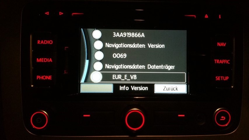
Press the setup button and hold for about 10 seconds.

The service screen appears. Select "Versions" now.

The last entry is the name of the map. For example "EUR_E_V8".
Perform map update
First of all organize the right SD-card.

Insert SD-Card with corresponding navigation data.
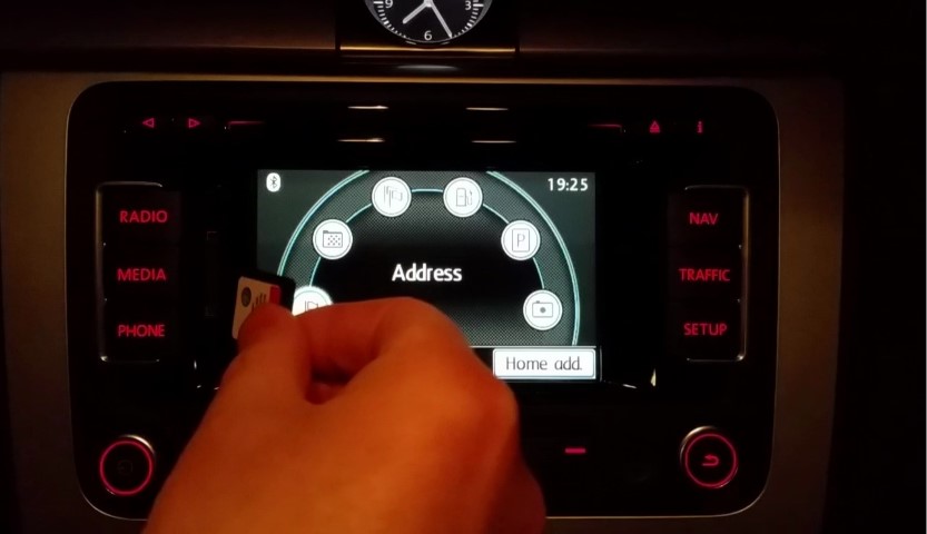
The RNS315 checks the SD-Card.

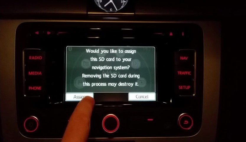
If the SD-Card is still virgin, the RNS315 asks if the SD-Card should be assigned to it. After assignment, the SD-Card is permanently married to the RNS315. And can no longer be used in another RNS315.
If you want to copy the data from the SD card into the RNS315, press "Install".
With "Use SD" the RNS315 directly accesses the navigation data of the SD-Card.
However, you should not do this because the navigation is slower and the SD-Card slot remains occupied.
That is why we choose "Install".

The installation takes about 120 minutes. There is no problem to switch off the ignition or the radio during the update.

It can happen that nobody is on the vehicle at the end of the installation. Then the RNS315 asleep again and no one sees the success of the installation. If the RNS315 is switched on again, the message "Successfully installed" no longer occurs, but the RNS315 wants to reinstall (overwrite)) or use the card immediately. Now just remove the card and everything is fine.
